There are some documents on how to do that around. If you want to set your freqs to higher like 30kHz you need to change these timer bits. However, the pwm pins of the arduino are being set with timer bits at the startup (around 490Hz or so and some of them are higher around 900). set the duty cycle around 128 to send a square wave. In order to avoid this you can use hardware PWM on the arduino.

It keeps the arduino busy in the main loop. The code given in the example is rather inefficient. The freq of the pulses determines the speed of the motor. Each pulse you send moves the motor 1 step. Stepper drives seems like use PFM (Pulse freq modulation). Gift the gift of Make: Magazine this holiday season! Subscribe to the premier DIY magazine todayĬommunity access, print, and digital Magazine, and more Share a cool tool or product with the community.įind a special something for the makers in your life.

Skill builder, project tutorials, and more Get hands-on with kits, books, and more from the Maker Shed Initiatives for the next generation of makers.

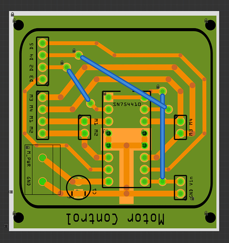
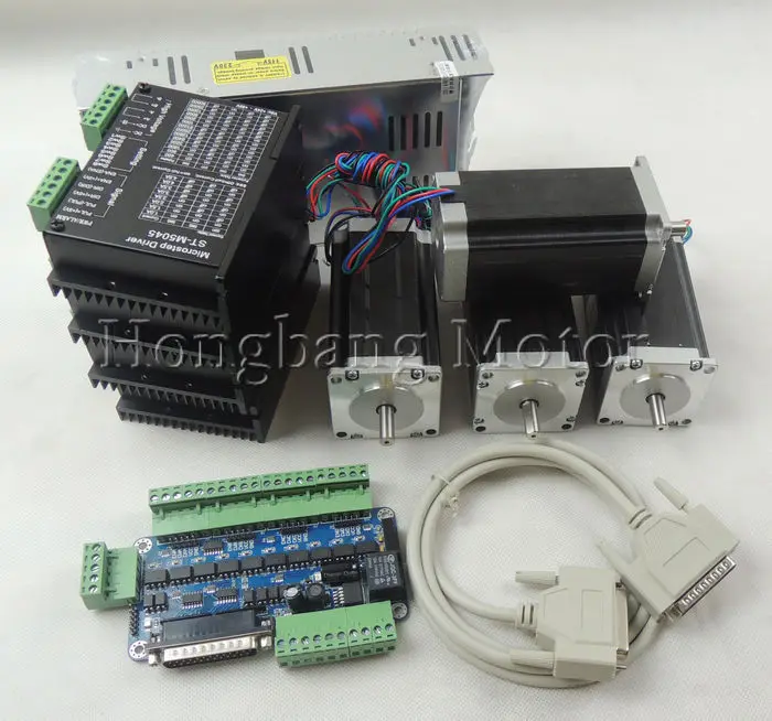
Membership connects and supports the people and projects that shape our future and supports the learning.A free program that lights children’s creative fires and allows them to explore projects in areas such as arts &Ĭrafts, science & engineering, design, and technology.Microcontrollers including Arduino and Raspberry Pi, Drones and 3D Printing, and more. Maker-written books designed to inform and delight! Topics such as.A smart collection of books, magazines, electronics kits, robots, microcontrollers, tools, supplies, and moreĬurated by us, the people behind Make: and the Maker Faire.Together tech enthusiasts, crafters, educators across the globe. A celebration of the Maker Movement, a family-friendly showcase of invention and creativity that gathers.The premier publication of maker projects, skill-building tutorials, in-depth reviews, and inspirational stories,.If you find parts that are broken post a link to them here and one of us will likely fix them for you. Print the footprint out on paper at one to one scale and try it against a real part before ordering boards. You need to check the pcb footprints of the parts before ordering boards because user supplied parts are of varying quality (and sometimes just plain wrong). I’m not sure what an additional power module is because it doesn’t appear in the parts list for the kit that google finds, unless you mean the ywrobot power supply board which is here: You now have the stepper driver and motor parts which appear to match those in the kit.

Right click on both parts and select export part to write them as an fzpz file. Downloading Motors.fzz and loading it in to Fritzing gets you the stepper driver and stepper motor in the temp parts directory. A search for “fritzing part unl2003” (which is the stepper driver) turns up


 0 kommentar(er)
